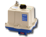
VALVECON ADC Failsafe Actuator
Continous Duty On/Off Electric Actuator

VALVCON ADC Series Electric Actuator
The VALVCON ADC Series electric actuator provide up to 3000 inch pounds of torque and can be equipped with internal back-up power to allow you to safely shut down your system in the event of an external power loss. Engineered to supply dependable valve and damper actuation, they can provide up to 10 complete cycles under their own internal power! Request Quote
VALVCON ADC Series Actuator Setup & Calibration: Something that appears very complicated, made a bit easier to understand in an 11 minute video! Give us a call for any of your actuation needs! (216) 631-6200
Features
- Choice Of 115VAC, 230VAC, 12VDC, 24VDC Or 24VAC Input Power
- Independent 115VAC, 230VAC, 12VDC, 24VDC Or 24VAC Control Signals
- Optional Internal Battery Back-Up
- Three-Position Operation
- Analog Position Output Signal (not present if using “Cam” Limit Type)
- Manual Push Button Control
- Single Or Multi Cycling Upon Loss of Line Power
- Switch Select Power “Fail” Position
- Locked Rotor Stall Protection
- On-board Battery Status Indicators
- Simple Digital Smart Set Functionality For Entering And Saving Precise End Of Travel Positions
NOTE: Some of the above features are only applicable with the optional Back-Up battery installed.
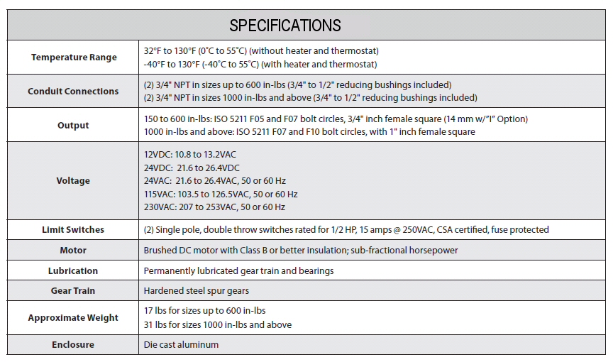
Specifications

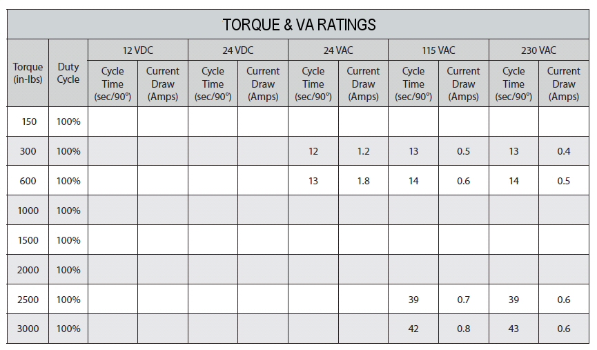
Technical

Standard Options
All ADC Series options are designed to be easily installed in the field. Options for all standard ADC Series actuators are universal and completely interchangeable with each enclosure size.
Option “H” – Tropical Heater and Thermostat P/N 99035, P/N 99036, P/N 99037, P/N 99038
The tropical heater and thermostat option is a self adhesive, resistant heater strip which is applied to primary gear-box. It installs with a plug-in connector and is recommended in high-humidity applications. The tropical heater option is also recommended installations that experience wide temperature swings in order to evaporate any condensation. Thermostat is pre-set to active at or below 90°F and deactivate at or above 110°F. The tropical heater draws 15 watts @ 115 VAC, 12 VDC and 24V; 40 watts at 230 VAC. This option can be installed in the field; for 115 VAC applications, order kit P/N 99035; for 230 VAC applications, order kit P/N 99036; for 12 VDC applications, order kit P/N 99037 and for 24 V applications, order kit P/N 99038.
Option “I” – ISO 5211 Output
150 – 600 in-lbs models are supplied with a 3/4″ female square output coupling; when the “I” option is selected they are supplied with a 14mm female square. 1000 – 3000 in-lbs models are supplied with a 1″ female square output coupling; when the “I” option is selected, 1000 in-lbs models are supplied with a 19mm female square and 1500 – 3000 in-lbs models are supplied with a 22mm female square. This option is factory installed only.
Option “S2” – Two Auxiliary Limit Switches P/N 99900
The extra switches and stainless steel cams provide dry contacts and are fully adjustable to trip at any position. They are often used for position indication or to interlock other devices (such as in sequencing operations). The
switches are single pole, double throw switches rated for 1/2 HP, 15 amps @250 VAC, CSA certified. Auxiliary switch
kit P/N 99900 is universal to all standard ADC Series actuators.
Option “T” – Heater and Thermostat P/N 99015, P/N 99016, P/N 99017, P/N 99018
The heater and thermostat option is a self-adhesive, resistance heater strip which is applied to the primary gearbox. It installs with a plug-in connector and is required in installations where the ambient temperatures drop below 32˚F. The heater option is also recommended in installations that experience wide temperature swings in order to evaporate any condensation. The thermostat is pre-set to activate at or below 40˚F and deactivate at or above 60˚F. The heater draws 15 watt @115 VAC, 12 VDC and 24 V; 40 watts @ 230 VAC. This option can be installed in the field; for 115 VAC order kit P/N 99015; for 230 VAC applications, order kit P/N 99016; for 12 VDC applications, order kit P/N 99017 and 24 V applications, order kit P/N 99018.
Option “Z” – Hand Wheel Override P/N 9097, P/N 9098
Standard ADC Series actuators are supplied with a plugged cover. Note that this is not recommended for ADC Series actuators equipped with the optional internal battery back-up. If the hand wheel override option is selected at the time of order a declutchable shaft and six-inch hand wheel are provided for manual positioning. This option can be replaced in the field; for 150 – 600 in-lbs models, order kit P/N 9097 and for 1000 – 3000 in-lbs models, order kit P/N 9098.
Voltage
115 VAC, 230 VAC, 24 VAC, 12 VDC and 24 VDC. ADC Series actuators are rated for full torque at +/- 10{c42715f24aabaeb6b4e3cb6160603ee9c5a794ce0020a316ef38081de5a321e6} of the nominal voltage at 50Hz or 60 Hz. ADC Series positioning actuators are rated continuous duty. (Note: At 50Hz the cycle time will increase by approximately 20{c42715f24aabaeb6b4e3cb6160603ee9c5a794ce0020a316ef38081de5a321e6}.)
Wiring
The identification label on each actuator specifies the model number, serial number, input power voltage and current requirements for the actuator. It is important to verify the correct input voltage prior to wiring the actuator.
There are three basic wiring schemes designed to operate the ADC Series On/Off Control Board options.
Wiring Schemes
Two Wire – On/Off Operation

Three Wire – Open/Stop/Close

Three Position – CW/MID/CCW

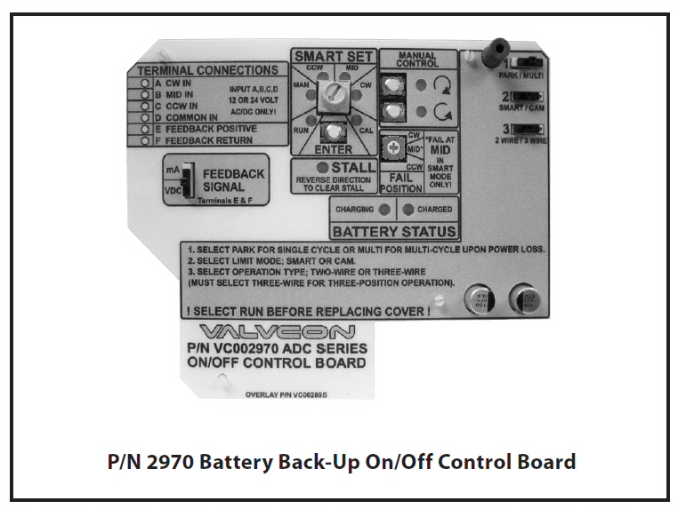
The universal ADC Series PC board includes both on/off and modulating functionality, and accepts both AC and DC power inputs.
Optional Internal Battery Back-up
The optional back-up power feature incorporates an internal battery pack that plugs right in to the PC board, which includes a built-in charging circuit, all fitting in the standard enclosure. Upon loss of external power the battery automatically activates as the main power supply and can immediately drive the actuator to a designated safe position or continue to respond to a control signal, if present.
It is capable of supplying sufficient power to ensure operation of the actuator during power outages. The battery voltage of a fully charged battery should read 13.6 volts as measured at the battery connector, (with the battery disconnected). This voltage will vary with temperature.
Backup On/Off Control Board


